

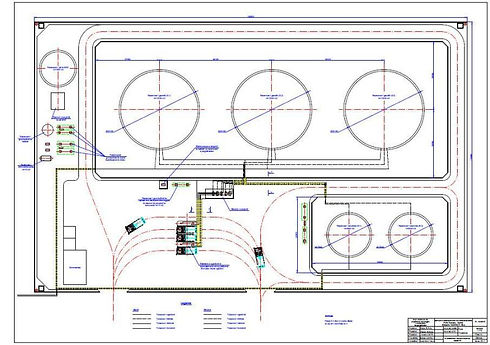
A preliminary plot plan is developed in the Feasibility Study phase in order to determine if a proposed location is suitable for the project. The preliminary plot plan also aides in the cost estimating effort.
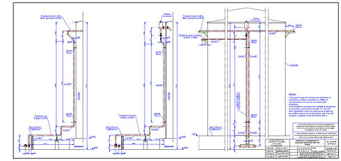

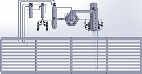
Process and utility pipe routing is a key step in the creative design of a process plant system. 3D pipe modeling is linked to P&ID drawings, which allows for better managed piping layouts. Piping is specification driven, allowing for the creation of isometric and orthographic documentation including automatic bills of materials. 3D Pipe routing of all process systems with piping ½” and larger. All routing of piping is critical in the overall plant design. The tools provided by Autodesk Plant Design Suite allow for clash and interference detection between piping, equipment and steel throughout early detailed design to final construction documents. Piping BOM’s and Steel weights can be generated at any stage of the design.
Utilizing the Autodesk Plant Design Suite, 2D and 3D Modeling is a key feature in developing our modular plant design layouts. P&ID allows for the fast creation of 2D piping and instrumentation diagrams, with custom features and properties stored to Vaestus standard drafting procedures. P&ID is database driven with smart object technology, linked to standard or customer driven piping specifications. 3D modeling of pipe and inline components are taken from the P&ID’s to allow for better job flow and minimize errors. 3D modeling also includes all equipment, steel and primary electrical equipment.

The first versions of various bills of materials (BOM) and material take-offs (MTO) including process, piping, electrical and structural are develop during the FEED stage.
These BOMs and MTOs are used for developing high quality project cost estimates and developing firm, fixed price quotations for the detailed engineering and fabrication stage of the project.
Preliminary piping material take-offs can be conducted at any stage of the FEED process. This is done by doing preliminary pipe route studies and extracting the material lists from the program. This program is resident within the AutoDesk Plant 3D program.
Piping spools and isometrics are generated from the 3D plant model. All piping runs are data and specification driven, therefore allowing for automatic generation of Bills of Materials for Isometric drawings.


Piping systems experience different types of loadings, categorized into three basic loading types — sustained, thermal and occasional loads.
Vaestus uses the CAESAR program to conduct pipe stress analysis.
Sustained load: these mainly consist of internal pressure and dead-weight. Dead-weight is from the weight of pipes, fittings, components such as valves, operating fluid or test fluid, insulation, cladding, lining, etc.
Thermal load: these refer to the “cyclic” thermal expansion or contraction of piping as it goes from one thermal state to another. When the pipe is “restrained” in the directions it wants to thermally deform (such as at equipment nozzles and pipe supports), the constraint on free thermal deformation generates cyclic thermal stresses and strains throughout the system. In order to avoid “fatigue” failure due to cyclic thermal loads, the piping system should be made flexible (and not stiff).
Occasional load: this third type of loads is imposed on piping systems by occasional events such as earthquake, wind or a fluid hammer.


