

We offer Systems Design for all mediums to be transported and stored of gases, liquids, solids, multiphase cases Gas-Liquid, Gas-Solids (pneumatic systems), Liquid-Solid (slurry transportation).
Piping and Instrumentation Diagrams (P&IDs) are an essential component of process design. P&IDs must show all the necessary piping and instrumentation that will be a part of the process. The P&IDs also establish a common protocol for communications between process engineers, piping engineers and instrumentation engineers. An example of a P&ID is shown on the right.


Vaestus uses Pipe flow expert software for conducting hydraulic calculations to determine the optimal line sizes for the gases and liquids flowing in the process.
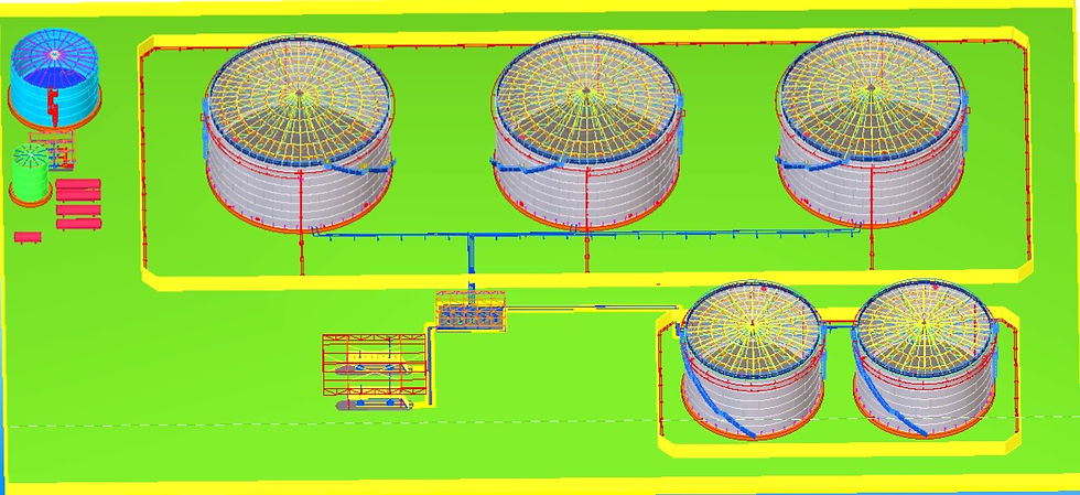
Process and utility pipe routing is a key step in the creative design of a process plant system. 3D pipe modeling is linked to P&ID drawings, which allows for better managed piping layouts. Piping is specification driven, allowing for the creation of isometric and orthographic documentation including automatic bills of materials. An example of a 2D pipe section is shown below.


Mita uses Pipe flow expert software for conducting hydraulic calculations to determine the optimal line sizes for the gases and liquids flowing in the process.
A typical process includes a large number of major equipment items such as pumps, compressors, vessels, reactors, heat exchangers, mass transfer columns, etc. Each one of these pieces of equipment have to be very carefully and diligently specified to accommodate maximum operating conditions. Nozzle locations and sizes and materials of construction have to be appropriately specified.


